More info
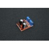
Detail about 555 Base Frequency Adjustable Oscillation Module
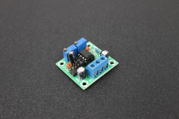
This little module is based on the ever-useful 555 timer IC. It features adjustable frequency over 4 separate ranges and you can also vary the duty cycle. This is ideal for producing timer and clock signals, of for flashing LEDs, or anywhere you would use a 555 timer in astable (oscillator) mode. The 555 timer IC is an integrated circuit used in a variety of timer, pulse generation, and oscillator applications. It can be used to provide time delays, as an oscillator, and as a flip-flop element. This NE555 frequency adjustable pulse generator Module utilizes the popular NE555 timer IC to generate pulses from about 4Hz to 1.3Khz, which can be used for experimental development, or driving a stepper motor, it would be also a good choice for learning & experiencing the analog RC circuits.
Specifications
- Input voltage: 5-15V DC
- Output amplitude: 4.2V - 11.4V (depending on input voltage)
- Input current: ≥15mA (when input 5V) or ≥35mA (when input 12V)
- Output LED indicator onboard (low level, LED is on, high level, LED is off)
- Selectable output frequency range section, covering the ranges below (values are approx and will vary with module slightly:LF: 1Hz-50Hz
- MF: 50Hz-1kHz
- MHF: 1kHz-10kHz
- HF: 10kHz-200kHz
- Size: 28mm x 37mm approx.
Instructions
- Input Voltage: 5V-15VDC.(when power supply is 5V , the output current can be 15mA around;when 12V power supply, the output current can 35mA around)
- Output amplitude: 4.2V V-PP(5v input) to 11.4V V-PP(12V input). (Different input voltage, the output amplitude will be different)
- Maximum output current: >=15mA (5V power supply, V-PP greater than50%),>=35mA (12V power supply, V-PP greater than 50%)
Application
- As a square wave signal generator,generates a square wave signal used for experimental development
- Used to drive a stepper motor
- Generate adjustable pulse for MCU
- Generate adjustable pulse to control circuitry associated
Reviews
No customer reviews for the moment.


