


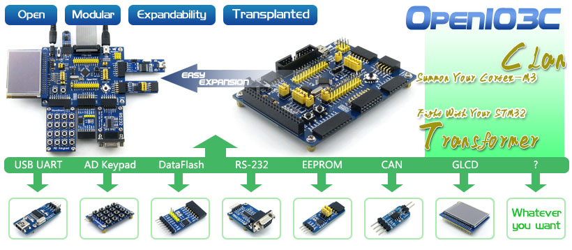
More info
-
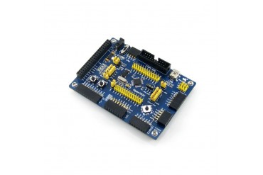
STM32 development board designed for STM32F103C series, features the STM32F103CBT6 MCU, and integrates various standard interfaces, pretty easy for peripheral expansions.
Overview
Open103C is an STM32 development board that features an STM32F103CBT6 device as the microcontroller. There are further expansions with various optional accessory boards for specific application. The modular and open design makes it the ideal for starting application development with STM32F family.
What's On Board
- STM32F103CBT6:the high performance STM32 MCU which features
- Core: ARM Cortex-M3 32-bit RISC
- Operating Frequency: 72MHz, 1.25 DMIPS/MHz
- Operating Voltage: 2-3.6V
- Package: LQFP48
- I/Os: 37
- Memories: 128kB Flash, 20kB RAM
- Communication Interfaces: 2 x SPI, 3 x USART, 2 x I2C, 1 x USB, 1 x CAN
- AD & DA converters: 2 x AD (12-bit, 1μs, shares 10 channels)
- Debugging/Programming: supports JTAG/SWD (serial wire debug) interfaces, supports IAP
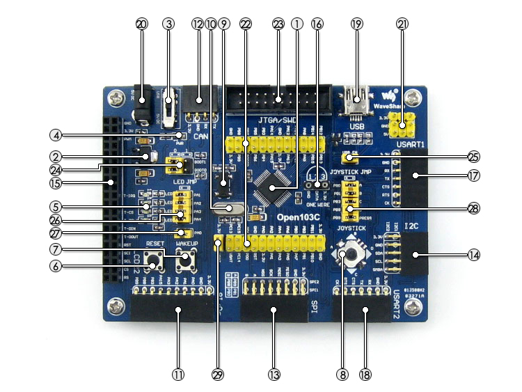
- AMS1117-3.3: 3.3V voltage regulator
- Power supply switch: 5V DC or USB
- Power indicator
- LEDs: for indicating I/O status or program debugging running state
- Reset button
- User key: for I/O input test
- Joystick: for I/O input test (five positions)
- 32.768K crystal oscillator: used for internal RTC, also supports clock calibration
- 8M crystal oscillator: enables the MCU run at 72M frequency by frequency multiplication
- 8 I/O Interface: easily connects to keypad, motor, etc.
- CAN interface: communicates with accessory board which features the CAN device conveniently
- SPI1 / SPI2 interface
- easily connects to SPI peripherals such as FLASH (AT45DBxx), SD card, MP3, etc.
- convenient for connecting AD module, thanks to the SPI1 alternative AD function
- short the jumper to enable the PC auto detection while USB connecting
- open the jumper to disable
- short the jumper to connect the LEDs to I/Os used in example code
- open the jumper to connect the LEDs to other custom pins via jumper wires
- short the jumper to connect the user key to I/Os used in example code
- open the jumper to connect the user key to other custom pins via jumper wires
- short the jumper to connect the joystick to I/Os used in example code
- open the jumper to connect the joystick to other custom pins via jumper wires
- short the jumper to use system power supply
- open the jumper to connect the VBAT to external power, such as battery
Photos
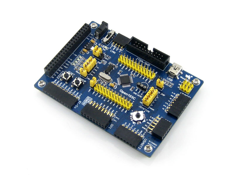
Open103C Development Board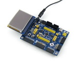
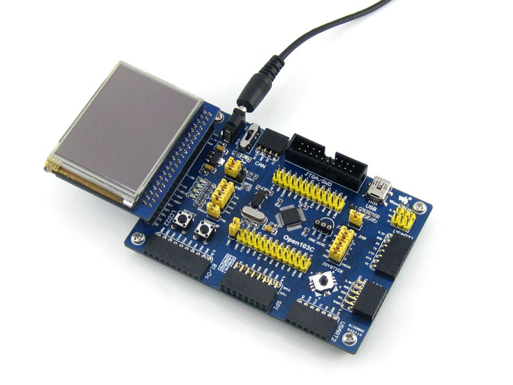
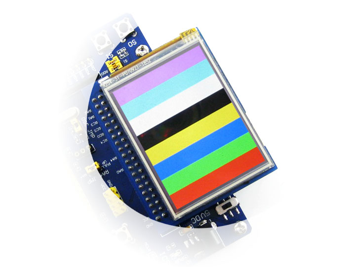
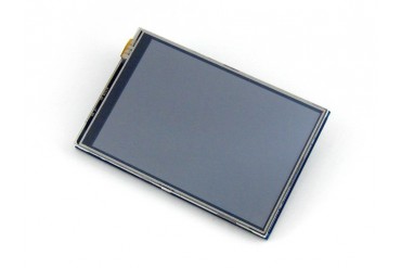
Connecting to touch screen LCD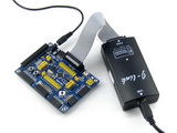
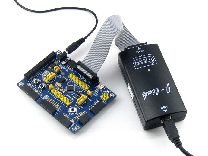
Connecting to debugger
Connecting to various peripherals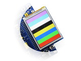
Connecting to touch screen LCD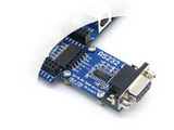
Connecting to RS232 Board via USART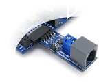
Connecting to RS485 Board via USART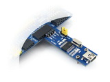
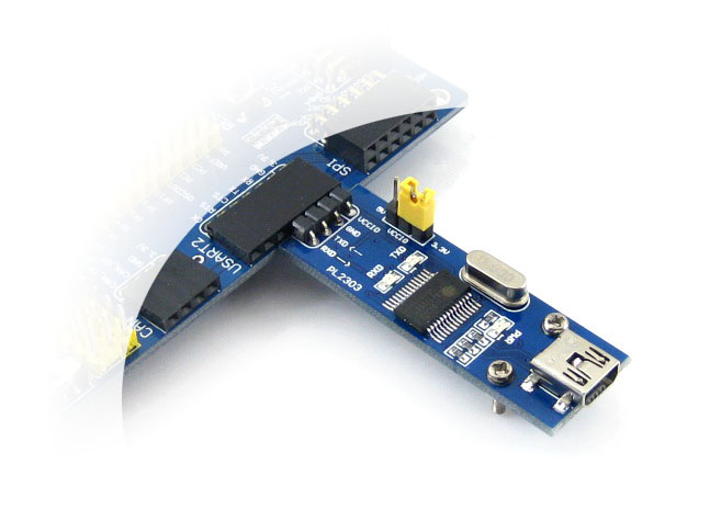
Connecting to USB UART Board via USART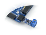
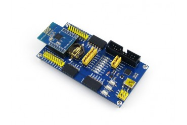
Connecting to CAN Board via CAN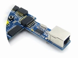
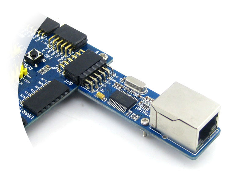
Connecting to Ethernet Board via SPI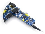
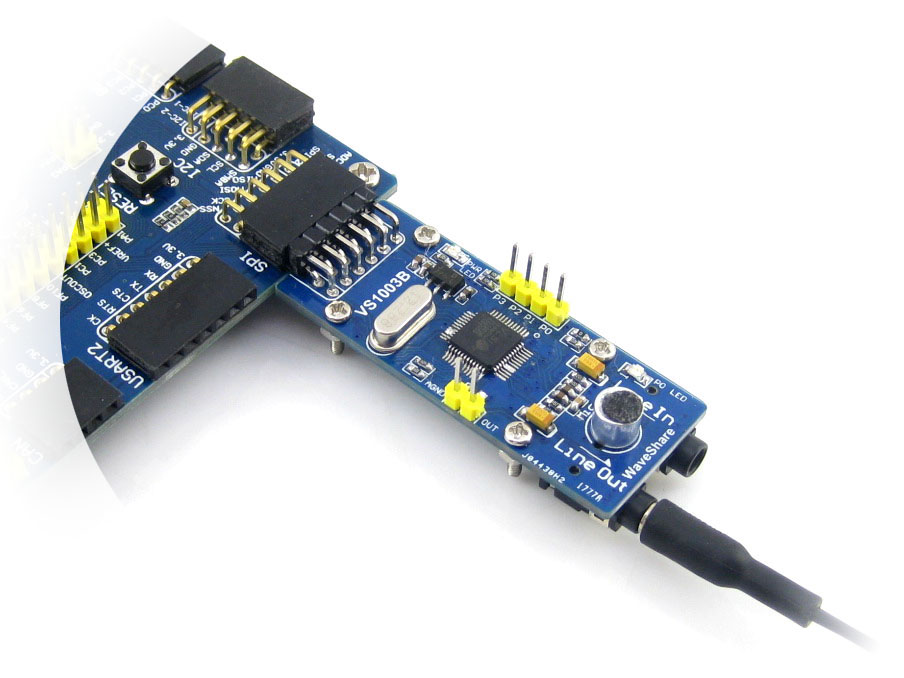
Connecting to VS1003B MP3 Board via SPI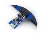
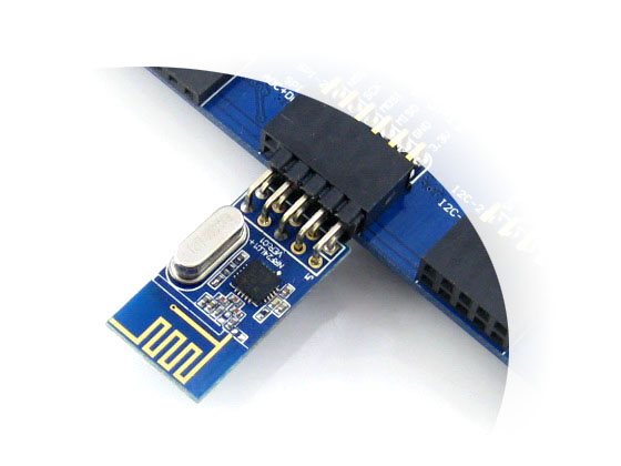
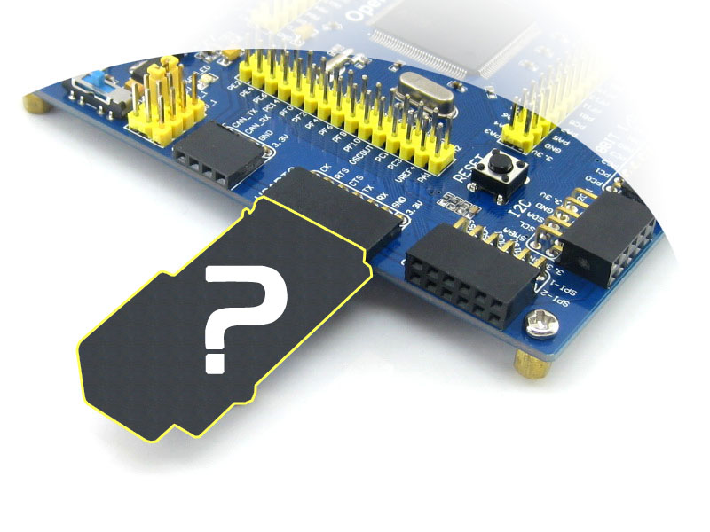
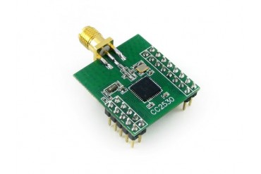
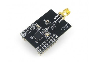
Connecting to NRF24L01 RF Board via SPI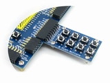
8 Push Buttons on the 8Bit I/O
Connecting to 5 IO Keypad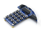
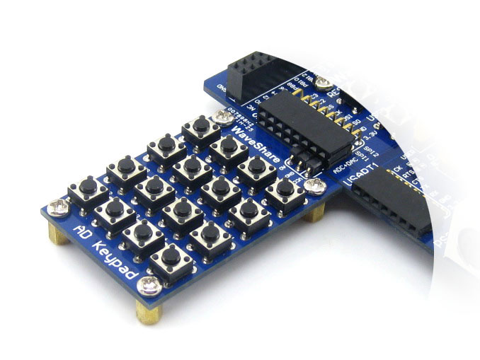
Connecting to AD Keypad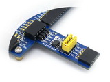
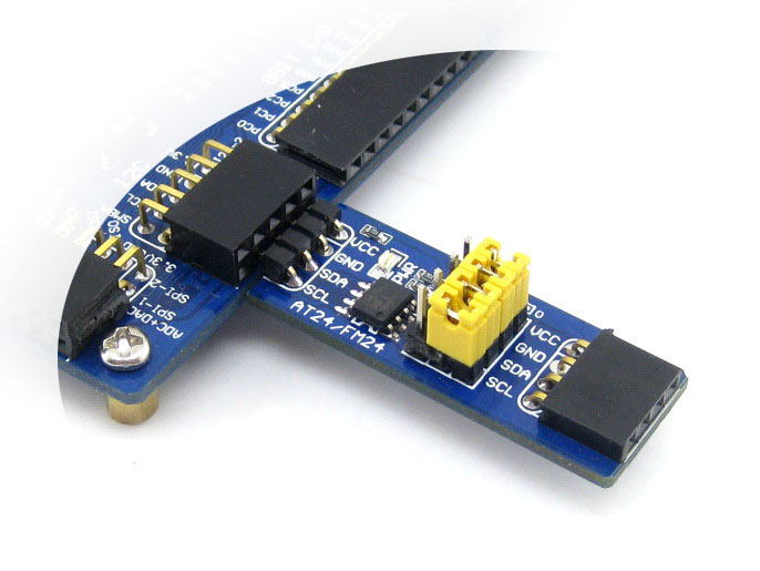
Connecting to EEPROM Board via I2C
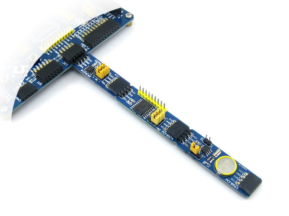
Multi I2C peripheral Module connected to the I2C bus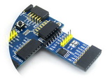
Connecting to DataFlash Board via SPI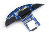
Connecting to Micro SD Board
Connecting to any accessory board you needNote:
The Open103C supports programming via STM32 USART bootloader, a USB TO UART accessory board is also provided in the package.
The Open103C does NOT integrate any debugging function, a debugger is required.
The Open103C Standard includes only ONE accessory board -- PL2303 USB UART Board (mini).JTAG/SWD Interfaces
The figure 1, and 2 show the header pinouts of JTAG/SWD interface
Figure 1. JTAG Header Pinout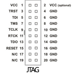 Figure 2. SWD Header Pinout
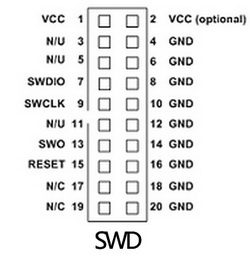
Development Resources
- Related software (KEIL etc.)
- Demo code (examples in C, μC/OS-II)
- Schematic (PDF)
- STM32 development documentations (Datasheet etc.)
- STM32F103CBT6:the high performance STM32 MCU which features


Reviews
No customer reviews for the moment.
30 other products in the same category:
-

WIFI-LPB100...
-
Core2530
-
XCore2530
-

Core51822
-
NRF51822...
-
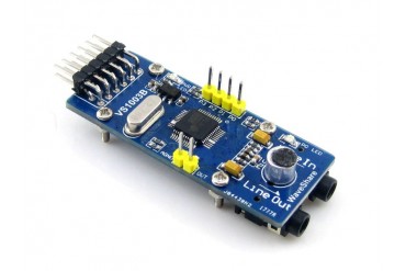
VS1003B MP3...
-
UDA1380 Board
-
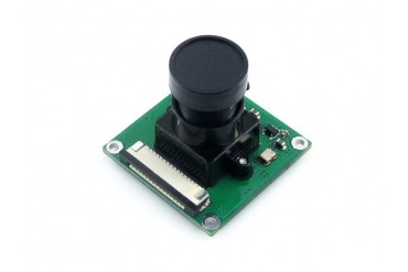
RPi Camera (B)
-
OV9655...
-

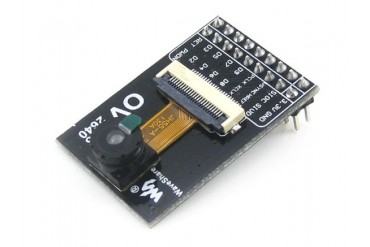
OV2640...
-
OV7670...
-
OV7670...
-

10 DOF IMU...
-
LSM303DLHC...
-
MAG3110 Board
-
UART...
-

Sensors Pack
-
7inch...
-
4.3inch...
-
3.2inch...
-
3.5inch RPi...
-

2.2inch...
-
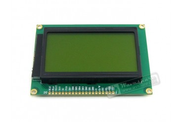
LCD12864-ST...
-
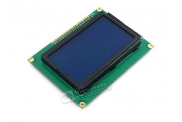
LCD12864-ST...
-
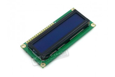
LCD1602...
-
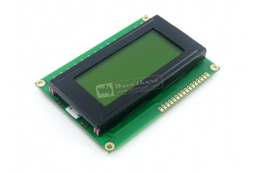
LCD1604 (5V...
-
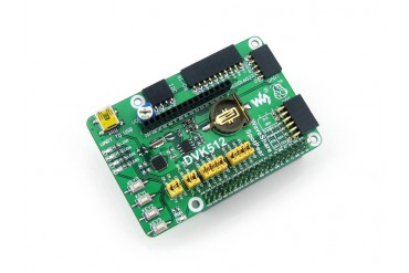
DVK512
-
ZB502
-

ZB600
-
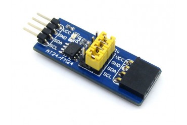
FM24CXX...