More info
-
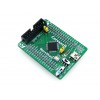
STM32 STM32F103RCT6 MCU core board, full IO expander, JTAG/SWD debug interface

Overview
Core103R is an STM32 MCU core board designed for STM32F103RCT6, supports further expansion. It is ideal for starting application development with STM32F family.
- Minimal ready-to-run system, integrates clock circuit, USB control circuit, USB connector, etc.
- All the I/O ports are accessible on the pin headers
- JTAG/SWD programming/debugging interface
- 2.54mm header pitch, allowed to be plugged-in your application board
What's On Board
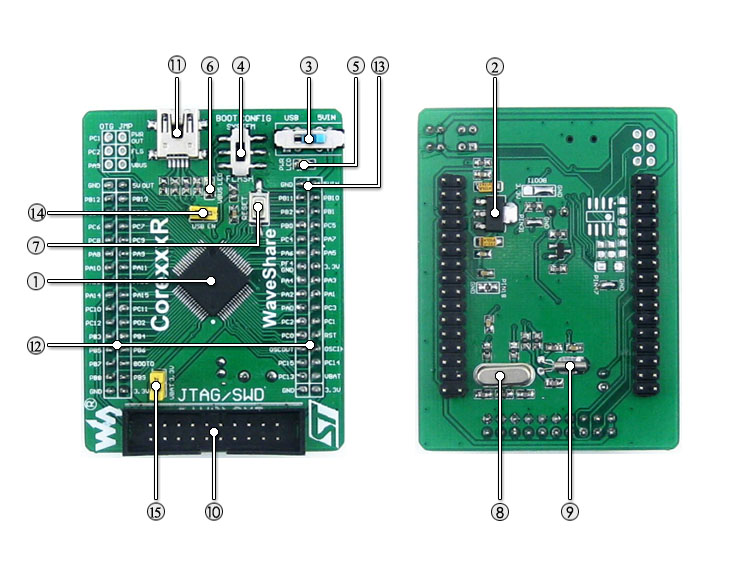
- STM32F103RCT6:the high performance STM32 MCU which features:
- Core: Cortex-M3 32-bit RISC
- Operating Frequency: 72MHz, 1.25 DMIPS/MHz
- Operating Voltage: 2-3.6V
- Package: LQFP64
- Memories: 256kB Flash, 48kB SRAM
- MCU communication Interfaces:
- 3xSPI, 5xUSART, 2xI2S, 2xI2C, 1xSDIO, 1xUSB, 1xCAN
- AD & DA converters: 3 x AD (12-bit, shares 16 channels); 2 x DA (12-bit)
- Debugging/Programming: supports JTAG/SWD (serial wire debug) interfaces, supports IAP
- AMS1117-3.3: 3.3V voltage regulator
- Power supply switch, powered from 5Vin or USB connection
- Boot mode selection, for configuring BOOT0 pin
- Power indicator
- VBUS LED
- Reset button
- 8M crystal
- 32.768K crystal, for internal RTC with calibration
- JTAG/SWD interface: for debugging/programming
- USB connector, used for establishing USB communication between PC and the STM32 development board
- MCU pins expander, VCC, GND and all the I/O pins are accessible on expansion connectors for further expansion
- 5Vin pinheader, 5V power supply input
- USB enable jumper
- short the jumper to enable USB function
- open the jumper to disconnect from related I/O port
- VBAT selection jumper
- short the jumper to use system power supply
- open the jumper to connect the VBAT to external power, such as battery
Photos
Note:
Mother board or programmer/debugger in the photo is NOT included in the price.
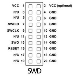
Core103R provides JTAG/SWD debugging interface, yet does NOT integrate any debugging function, a debugger is required.JTAG/SWD Interfaces
The figure 1, figure 2 shows the header pinout of JTAG, SWD interface respectively
Figure 1. JTAG Header Pinout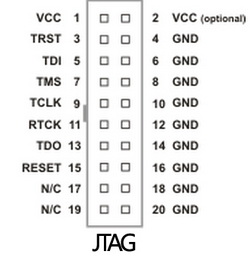 Figure 2. SWD Header Pinout
Development Resources
- Related software (KEIL etc.)
- Examples in C
- Schematic (PDF)
- Development documentations
Wiki: www.waveshare.com/wiki/Core103R
Dimensions

Reviews
No customer reviews for the moment.


